When I originally built the air quality monitor for my school I used the Things Network, a public LoRaWAN radio network for low power devices to send data to the internet. This year a new version of the back end came out, called The Things Stack (aka V3). As a result, they are shutting down the V2 back end, which is what the monitor was using, at the end of the year.
The V2 back end was not fully compliant with the LoRaWAN specification. The specification requires that the network sends downlink messages to devices called MAC commands to configure details such as which channels they use. V2 didn’t bother with this, and relied on these details being hard coded into devices.
However, V3 now implements the full specification. This means that devices can receive configuration details from the network. This sounds good, but the original monitor didn’t support it. It used a library called TinyLoRa, which only supported transmitting data, not receiving it.
This was a problem, because after a downlink message is sent the device is expected to reply with an acknowledgement. Since the device wouldn’t receive the messages, it wouldn’t acknowledge them. This would have led to the network sending the same message repeatedly, believing there was a transmission error, which would have quickly burned through the fair access policy allowance of 10 downlinks a day.
To solve this, all that theoretically needed to be done was upgrade to LMIC, a LoRaWAN compliant library. However, the Arduino Pro Mini doesn’t have enough program storage space to store the much larger LMIC alongside the other libraries it needed. As a result, I had to upgrade to using an STM32 blue pill with 64kB of program memory, twice as much as the Pro Mini – this is one of the things I have been doing during the summer holidays.
To simplify the hardware changes, I designed a PCB to slot into the 3D printed frame where the Pro Mini’s matrix board originally sat. It was my first attempt at PCB design.
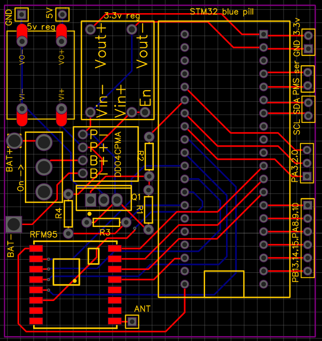
I used EasyEDA and followed a Youtube tutorial. It was much more fun than soldering matrix boards and much easier than I expected.
Once the PCB was set up I created a new program in PlatformIO derived from the LMIC-Node example on GitHub.
I applied what I had learnt from the operation of the previous version to improve this version of the monitor. Here are some of the improvements I made:
- I set up a voltage divider to measure the battery voltage instead of just measuring the Vcc voltage. This allowed me to make the monitor transmit less often when the battery is low, allowing the battery to last longer in periods of poor weather.
- I stopped measuring methane and ammonia levels – the data from the old monitor showed that they were almost always zero, they weren’t used for anything, and they used up 8 bytes in each packet. Additionally, these parts of the Multichannel gas sensor took longest to heat up, which is why I had to leave the sensor turned on constantly on the old version. Removing them meant I could power off the sensor most of the time with a MOSFET and only power it on for a few minutes before taking a reading.
- From analysing the data I found that the CCS811 calculated eCO2 by multiplying tVOC by a constant factor and adding a constant. I used Excel to find these constants, and then I could calculate eCO2 on the server side instead of transmitting it from the monitor, saving another two bytes.
- After asking about the idea on the EEVBlog forum, I removed the battery protector which cut off the power when the voltage dropped too low and instead got the monitor to hibernate when the battery is lower than a threshold. This improved the efficiency of the monitor because no energy is used to power the protector.
After these changes the size of each packet decreased from 28 bytes to 18 bytes and the power consumption when sleeping reduced from around 67mA (due to having to leave the multichannel gas sensor on for the methane and ammonia preheating) to 0.38mA, which I’m very happy with. This should mean it can last significantly longer in poor weather.
Another feature I’m pretty pleased with is that, since the monitor can receive downlinks, I set it up to trigger a software reset when it receives a single byte 0x9D, which could come in useful if it starts to malfunction. (I picked 0x9D because this was one of the “Halt and Catch Fire” opcodes of the 1974 MC6800 microprocessor)
I’m happy with the result of the upgrades and I’ve also learned a lot about the STM32 microcontroller and about PCB design.
