Recently I’ve been watching some of Ben Eater’s videos on Youtube about building a computer following the SAP-1 architecture. To practice using TypeScript I decided to try and create a simulator.
I wanted to be able to see what was going on, so I used p5.js to create a graphical interface showing the state of the different components.
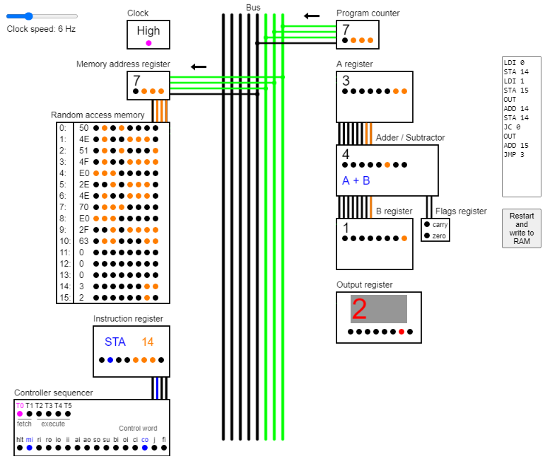
Here’s what I ended up with:
You can try running the simulator yourself here: https://brychanthomas.github.io/SAP-1-Simulator/ . You can also have a look at the code here: https://github.com/brychanthomas/SAP-1-Simulator .
You can adjust the clock speed using the slider in the top left corner, and you can write assembly programs and write them to the RAM using the textarea and button on the right.
The default program that is running when the page loads calculates the Fibonacci sequence, restarting when it goes over 255 because the computer can only store 8 bit numbers.
The computer
The computer is a simulation based on Ben Eater’s implementation of the SAP-1 (Simple As Possible 1) architecture by Albert Malvino in the book Digital Computer Electronics. (I’d like to look at the original book but am yet to find a library that has it).
I’ve simplified Ben Eater’s physical implementation slightly by having all of the control signals active high instead of a mix of active low and active high.
The architecture is made up of 11 components with 16 control signals.
| Component | Description | Control signals |
| Clock | Alternates between high and low at a specific frequency to coordinate the timings of the computer’s activities. | halt |
| Memory address register | Stores the RAM address that is being read from or written to. | mar in |
| Random access memory | Stores 16 bytes of machine code instructions and data. | ram in, ram out |
| Instruction register | Stores the instruction that is currently being executed so that the controller sequencer can issue the correct control signals at a given time step. | instruction in, instruction out |
| Controller sequencer (or control unit) | Allows the computer to carry out instructions by issuing control signals to coordinate how the other components interact. It carries out each instruction by counting through six time steps and writing control signals using pre-programmed microcode logic that is based upon the instruction register’s contents, the time step and the flags register. | |
| Program counter | A counter that stores which instruction should be fetched and executed next. | counter out, counter increment, jump |
| A register | A general purpose register that is the first input to the adder/subtractor. The ADD and SUB instructions store the result in this register. | a in, a out |
| Adder/ subtractor | The adder/subtractor either adds the contents of the A and B registers together or subtracts them based on the subtract control signal. It isn’t an ALU because it can’t carry out logical operations. | sum out, subtract |
| B register | The B register is the second input to the Adder/ subtractor. The ADD and SUB instructions store the number to be added or subtracted in this register. | b in |
| Output register | This register stores the output of the computer, which is shown on a display. The OUT instruction writes the contents of the A register here. | output in |
| Flags register | Stores the carry and zero flags from the adder/subtractor. These are used by the controller sequencer in conditional jump instructions JC and JZ. | flags in |
There are 11 assembly instructions the computer can execute:
| Instruction | Description |
|---|---|
| NOP | Do nothing |
| LDA | Load the value in the specified memory address into the A register. |
| ADD | Add the value in the specified memory address with the value in the A register, storing the result in the A register. |
| SUB | Subtract the value in the specified memory address from the value in the A register, storing the result in the A register. |
| STA | Store the value in the A register in the specified memory address. |
| LDI | Immediately load the specified value into the A register without involving memory. |
| JMP | Jump to the specified instruction number. |
| JC | Jump to the specified instruction number if the carry flag is set. |
| JZ | Jump to the specified instruction number if the zero flag is set. |
| OUT | Load the value in the A register into the output register to be shown on a display. |
| HLT | Stop the computer clock. |
Graphics
A coloured line or circle represents a 1, and a black line or circle represents a 0.
Connections between the components and the bus are only shown when they are actively reading or writing to it. This represents the tri-state buffers, which electrically disconnect the components from the bus when the control bits dictate that they are not reading or writing.
The arrows above connections show whether the component is reading or writing. For example, in the diagram above, the program counter is writing the number 7 to the bus while the memory address register is reading and storing this value.
I implemented the graphics separately to the computer simulator itself so that the computer could still be used in other contexts without any modification. To do this I created a computerState object that tracks the state of components and calls the relevant graphics functions whenever something changes.
Implementation
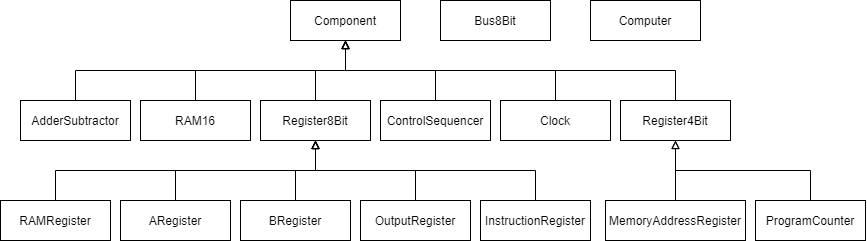
I implemented each component of the computer as a class and then created a Computer class that combined all these together to form the full computer. I used inheritance from an abstract Component class to ensure that I kept a uniform interface for all the components.
Up until now I have created JavaScript projects by having different files and then including them all using the HTML script tags. However, this was more difficult to do with TypeScript because the transpiler would not know that the files were linked together like this and would give error messages when I tried to use variables and classes from other files.
As a result, I decided to try and implement the computer as an ES6 module with import and export statements. Although this was confusing at first and it took me a while to get it to work I have learned how to get TypeScript to transpile correctly and how to use a module, which I am happy about.
I have enjoyed watching Ben Eater’s videos and creating this simulation. It was nice to see the theory I’d done in GCSE Computer Science such as the fetch-execute cycle and components such as the program counter in action, even on such a small scale.
